Page 30 - ExpansionJointsCatalog2010
SEO Version


PROCO
™
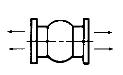
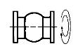
Series 251 Products Are
Designed To Absorb Different
Movements Concurrently.
Axial Compression
Axial Elongation
Angular Movement
Bending Of The Centerline
Torsional Movement
Rotation About The Centerline (Twist)
Lateral Movement
Shear Or Perpendicular To Centerline
Absorbing Vibration
DISTRIBUTED BY:
Retaining
Rings
Rubber
Washer
Steel
Washer
Nominal
Pipe Size
Joint I.D.
Standard
Pipe
Flange
Optional
Compression Sleeve
Control Rod Bolt Circle
Flange/Retaining Ring O.D.
Bolt Circle
Equally Spaced
Bolt Holes
Bolt Circle
Split
A
A
Neutral Length
Retaining Rings
Section AA
A
Equally Spaced
Bolt Holes
Bolt Circle
A
Bolt
Holes
Dia.
Flange & Ret. Ring O.D.
Nominal Pipe Size
Joint I.D.
Figure 1: Detail Of Style 251/BT
Ret. Ring I.D.
Control
Rod
Plate
PTFE/FEP
Liner
PTFE & FEP lined rubber expansion joints
TOLL-FREE PHONE: (800) 344-3246
FACSIMILE: (209) 943-0242
(209) 943-6088
email: sales@procoproducts.com
website: http://www.procoproducts.com
NATIONWIDE AND CANADA
INTERNATIONAL
2431 North Wigwam Dr. (95205)
P.O. Box 590 • Stockton, CA
95201-0590 • USA
Notes:
1. The degree of angular movement is based on the maximum rated extension.
2. Torsional movement is expressed when the expansion joint is a neutral length.
3. To determine “end thrust”, multiply thrust factor by operating pressure of system.
4. Pressure rating is based on 170
°
F operating temperature. At higher temperature
the pressure rating is slightly reduced.
5. Weights are approximate.
6. Control unit weight consists of one rod, four washers, three nuts and two control
rod plates. Multiply number of control units needed for application (as specified in
the Fluid Sealing Association Technical Handbook) to determine correct weights.
7. Dimensions shown are in accordance with 125/150# standards of ANSI B-16.1,
B-16.24, B-16.5; AWWA C-207 Table 1 and 2 Class D.
8. 1" I.D. through 12" I.D. have white PTFE liners.
12" I.D. through 48" I.D. have clear FEP liners.
9. Teflon liner extends to bolt holes’ center line only.
10. Available in filled arch configuration only.
PROCO PRODUCTS, INC.
Warning: Expansion joints may operate in pipelines or equipment carrying
fluids and/or gases at elevated temperatures and pressures. Normal precau-
tions should be taken to make sure these parts are installed correctly and
inspected regularly. Precautions should be taken to protect personnel in the
event of leakage or splash. Note: Piping must be properly aligned and an-
chored to prevent damage to an expansion joint. Movement must not exceed
specified ratings and control units are always recommended to prevent dam-
age in the event other anchoring in the system fails. Properties applications
shown throughout this data sheet are typical. This information does not con-
stitute a warranty or representation and we assume no legal responsibility or
obligation with respect thereto and the use to which such information may
be put. Your specific application should not be undertaken without indepen-
dent study and evaluation for suitability.
36
2.5
9
3
(65)
4
(80)
5
(100)
6
(125)
8
(150)
10
(200)
12
(250)
14
(300)
16
(350)
18
(400)
20
(450)
24
(500)
30
(600)
(750)
6
(150)
8
(200)
10
(250)
1.5
(38)
1.7
(44)
0.5
(13)
0.7
(17)
20.6
°
17.4
°
13.2
°
12.0
°
11.1
°
8.4
°
8.1
°
7.3
°
6.3
°
5.9
°
5.3
°
4.8
°
3.9
°
3.8
°
3.1
°
1
°
1
°
1
°
1
°
26
(660)
7.5
(3.4)
4.5
(2.0)
2.8
(1.3)
4.75
(120.65)
4 0.750
(19.05)
4
8
8
8
8
12
12
12
16
16
20
20
28
32
0.875
(22.23)
1.000
(25.40)
0.5
(13)
0.7
(17)
1.0
(25)
150
(10.0)
150
(10.0)
150
(10.0)
150
(10.0)
150
(10.0)
125
(8.8)
125
(8.8)
26
(660)
26
(660)
26
(660)
26
(660)
26
(660)
26
(660)
26
(660)
26
(660)
26
(660)
26
(660)
26
(660)
26
(660)
26
(660)
26
(660)
9.5
(4.3)
13.0
(5.9)
14.0
(6.4)
16.0
(7.3)
20.0
(9.1)
28.0
(12.7)
44.0
(20.0)
50.0
(22.7)
59.0
(26.8)
68.0
(30.8)
79.0
(35.8)
91.0
(41.3)
129.0
(58.5)
160.0
(72.6)
5.5
(2.5)
8.0
(3.6)
8.5
(3.9)
9.5
(4.3)
14.5
(6.6)
17.0
(7.7)
24.5
(11.0)
27.0
(12.3)
33.5
(15.2)
34.0
(15.5)
38.0
(17.3)
63.0
(28.6)
76.0
(34.5)
2.8
(1.3)
2.8
(1.3)
4.0
(1.8)
4.0
(1.8)
8.0
(3.6)
10.0
(4.5)
10.0
(4.5)
12.0
(5.4)
15.0
(6.8)
16.5
(7.2)
16.5
(7.2)
20.0
(9.0)
43.0
(19.5)
7.0
(177.8)
7.5
(190.5)
9.0
(228.6)
10.0
(254.0)
11.0
(279.4)
13.5
(342.9)
16.0
(406.4)
19.0
(482.6)
21.0
(533.4)
23.5
(596.9)
25.0
(635.0)
27.5
(698.5)
32.0
(812.8)
38.8
(984.3)
5.50
(139.7)
6.00
(152.4)
7.50
(190.5)
8.50
(215.9)
9.50
(241.3)
11.75
(298.4)
14.25
(362.0)
17.00
(431.8)
18.75
(476.3)
21.25
(539.8)
22.75
(577.9)
25.00
(635.0)
29.50
(749.3)
42.75
(1085.9)
0.750
(19.05)
0.750
(19.05)
0.875
(22.23)
0.875
(22.23)
1.000
(25.40)
1.125
(28.58)
1.125
(28.58)
1.250
(31.75)
1.250
(31.75)
1.375
(34.93)
1.625
(41.28)
1.0
(25)
48
(900)
(1200)
12
(300)
2
9
1.5
9
1
9, 10
(50)
(40)
(25)
25.2
°
29.9
°
35.8
°
0.5
(13)
0.5
(13)
0.5
(13)
0.5
(13)
0.5
(13)
0.5
(13)
0.7
(17)
0.7
(17)
0.7
(17)
0.7
(17)
0.7
(17)
0.7
(17)
0.7
(17)
0.7
(17)
0.7
(17)
0.7
(17)
1.0
(25)
1.0
(25)
1.0
(25)
1.0
(25)
1.0
(25)
1.0
(25)
1.0
(25)
1.0
(25)
1.0
(25)
1.0
(25)
0.7
(17)
0.7
(17)
0.7
(17)
0.7
(17)
0.7
(17)
0.7
(17)
0.7
(17)
Table 2: Sizes • Movements • Pressures • Weights • Drilling
EXPANSION
JOINT SIZE
Nom. I.D. x
Inch / (mm)
NEUTRAL
LENGTH
Inch / (mm)
Flange Dimensions and Drilling
7
Weights in lbs / (kgs)
5
Operating Conditions
4
Axial
Compression
Inch / (mm)
Axial
Extension
Inch / (mm)
Lateral
Deflection
Inch / (mm)
Angular
1
Deflection
Degrees
Torsional
2
Rotation
Degrees
Thrust Factor
3
In2 / (cm2)
Positive
PSIG / (Bar)
Vacuum
Inches of Hg /
(mm of Hg)
Joint
Assembly
Retaining
Ring Set
Control Unit
6
Assembly
O.D. of Exp.
Joint / Ring
Inch / (mm)
Bolt Circle
Inch / (mm)
Number of
Holes
Size of Holes
In
ch / (mm)
251/BT Movement Capability: From Neutral Position
6.0
(152.4)
26
(660)
7.0
(3.2)
4.0
(1.8)
2.8
(1.3)
4 0.750
(19.05)
5.0
(127.0)
26
(660)
6.0
(2.7)
2.5
(1.1)
2.3
(1.0)
3.88
(98.6)
4 0.625
(15.88)
4.3
(108.0)
225
(15.5)
26
(660)
3.0
(1.4)
2.0
(0.8)
2.3
(1.0)
3.13
(79.5)
4 0.625
(15.88)
2.7
°
1
°
44
100
(7.0)
26
(660)
244.0
(110.7)
132.0
(59.9)
44.0
(20.0)
59.5
(1511.3)
56.00
(1142.4)
1.625
(41.28)
1
°
1
°
1
°
1
°
1
°
1
°
1
°
1
°
1
°
1
°
1
°
1
°
1
°
1
°
225
(15.5)
225
(15.5)
225
(15.5)
225
(15.5)
225
(15.5)
225
(15.5)
225
(15.5)
225
(15.5)
225
(15.5)
225
(15.5)
48.0
(21.8)
29.5
(13.3)
46.0
(1168.4)
36.00
(914.4)
1.375
(34.93)
3.1
(20)
4.9
(32)
7.1
(46)
12.6
(81)
19.6
(127)
28.3
(182)
50.3
(324)
78.5
(507)
113.1
(730)
153.9
(993)
201.1
(1297)
254.5
(1642)
314.2
(2027)
452.4
(2919)
706.9
(4560)
1017.9
(6567)
1809.6
(11675)
1.8
(11)
0.8
(5)
Powered by FlippingBook Publisher