Page 109 - bannerAnvil2010PipeFittingsCatalog2010
SEO Version


www.anvilintl.com
109
forged steel fittings
Malleable Iron
Cast Iron
Small Steel
Fittings
Pipe Nipples &
Pipe Couplings
Forged Steel
Fittings & Unions
Anvilets
Catawissa
J.B. Smith Products
Carton Information
Forged Steel Fittings
Class 3000 Socket Weld
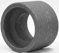
figure 2156
Reducing Couplings
Size
B
Socket Dia.
D
Bore Dia.
E
J
Socket Depth
Minimum
Unit Weight
Lowest Reduction
NPS DN NPS DN in
mm in
mm in
mm in
mm lbs
kg
1
⁄
4
8
1
⁄
8
6 .575
.555
14.6
14.2 0.130 3.30 .394
.334
10.0
8.5 0.25 6.5 0.38 9.5
3
⁄
8
10
1
⁄
8
6 .710
.690
18.0
17.6 0.138 3.50 .523
.463
13.3
11.8 0.25 6.5 0.38 9.5
1
⁄
2
15
1
⁄
8
6 .875
.855
22.2
21.8 0.161 4.09 .652
.592
16.6
15.0 0.38 9.5 0.38 9.5
3
⁄
4
20
1
⁄
8
6 1.085
1.065
27.6
27.2 0.168 4.27 .854
.794
21.7
20.2 0.38 9.5 0.50 12.5
1 25
1
⁄
8
6 1.350
1.330
34.3
33.9 0.196 4.98 1.079
1.019
27.4
25.9 0.50 12.5 0.50 12.5
1
1
⁄
4
32
1
⁄
4
8 1.695
1.675
43.1
42.7 0.208 5.28 1.410
1.350
35.8
34.3 0.50 12.5 0.50 12.5
1
1
⁄
2
40
1
⁄
4
8 1.935
1.915
49.2
48.8 0.218 5.54 1.640
1.580
41.6
40.1 0.50 12.5 0.50 12.5
2 50
1
⁄
2
15 2.426
2.406
61.7
61.2 0.238 6.04 2.097
2.037
53.3
51.7 0.75 19.0 0.62 16.0
2
1
⁄
2
65
1
⁄
2
15 2.931
2.906
74.4
73.9 0.302 7.67 2.529
2.409
64.2
61.2 0.75 19.0 0.62 16.0
3 80 1
1
⁄
2
40 3.560
3.535
90.3
89.8 0.327 8.30 3.128
3.008
79.4
76.4 0.75 19.0 0.62 16.0
4 100 2 50 4.570
4.545
115.7
115.2 0.368 9.35 4.086
3.966
103.8
100.7 0.75 19.0 0.75 19.0
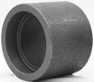
figure 2155
Half Couplings
Size
B
Socket Dia.
D
Bore Dia.
F
J
Socket Depth
Minimum
Unit Weight
NPS
DN
in
mm in
mm in
mm in
mm lbs
kg
1
⁄
8
6
.440
.420
11.2
10.8
.299
.239
7.6
6.1 0.62 16.0 0.38 9.5 0.09 0.04
1
⁄
4
8
.575
.555
14.6
14.2
.394
.334
10.0
8.5 0.62 16.0 0.38 9.5 0.12 0.05
3
⁄
8
10 .710
.690
18.0
17.6
.523
.463
13.3
11.8 0.69 17.5 0.38 9.5 0.23 0.10
1
⁄
2
15 .875
.855
22.2
21.8
.652
.592
16.6
15.0 0.88 22.5 0.38 9.5 0.28 0.13
3
⁄
4
20 1.085
1.065
27.6
27.2
.854
.794
21.7
20.2 0.94 24.0 0.50 12.5 0.43 0.20
1
25 1.350
1.330
34.3
33.9
1.079
1.019
27.4
25.9 1.12 28.5 0.50 12.5 0.66 0.30
1
1
⁄
4
32 1.695
1.675
43.1
42.7
1.410
1.350
35.8
34.3 1.19 30.0 0.50 12.5 1.10 0.50
1
1
⁄
2
40 1.935
1.915
49.2
48.8
1.640
1.580
41.6
40.1 1.25 32.0 0.50 12.5 1.06 0.48
2
50 2.426
2.406
61.7
61.2
2.097
2.037
53.3
51.7 1.62 41.0 0.62 16.0 2.15 0.98
2
1
⁄
2
65 2.931
2.906
74.4
73.9
2.529
2.409
64.2
61.2 1.69 43.0 0.62 16.0 3.70 1.68
3
80 3.560
3.535
90.3
89.8
3.128
3.008
79.4
76.4 1.75 44.5 0.62 16.0 6.00 2.72
4
100 4.570
4.545
115.7
115.2
4.086
3.966
103.8
100.7 1.88 48.0 0.75 19.0 8.00 3.63
D
B
J
F
D
B
E
J
Note:
When the pipe is seated against the bottom of the socket prior to welding, to prevent possible cracking of the fllet welds, it is recommended that the pipe be withdrawn approximately
1
⁄
16
in
(1.6mm)
away
from contact with the bottom of the socket before starting the weld.
Average of socket wall thickness around periphery shall be no less than listed values. The minimum values are permitted in localized areas.
Powered by FlippingBook Publisher